Simple DC Voltage and Current limiter
Protect circuits using LM317
What happened is this: I made my first low-cost photovoltaic system, a small 12V, 4 x 50W 36-cell panels to power a bunch of devices with an inverter (notebook, cell charger, a couple of lights). I’m using an entry level 20A 12/24V MPPT Regulator (used at 12V) which receives current from the panels and charges my AGM battery pack; as many already know, it does that using two input connectors (+/-) for the panels and has two output connectors (+/-) for the batteries. All the regulators have other two connectors (yes, again +/-) on which you can connect a 12V DC Load, it could be a lamp or something that doesn’t require too much current.
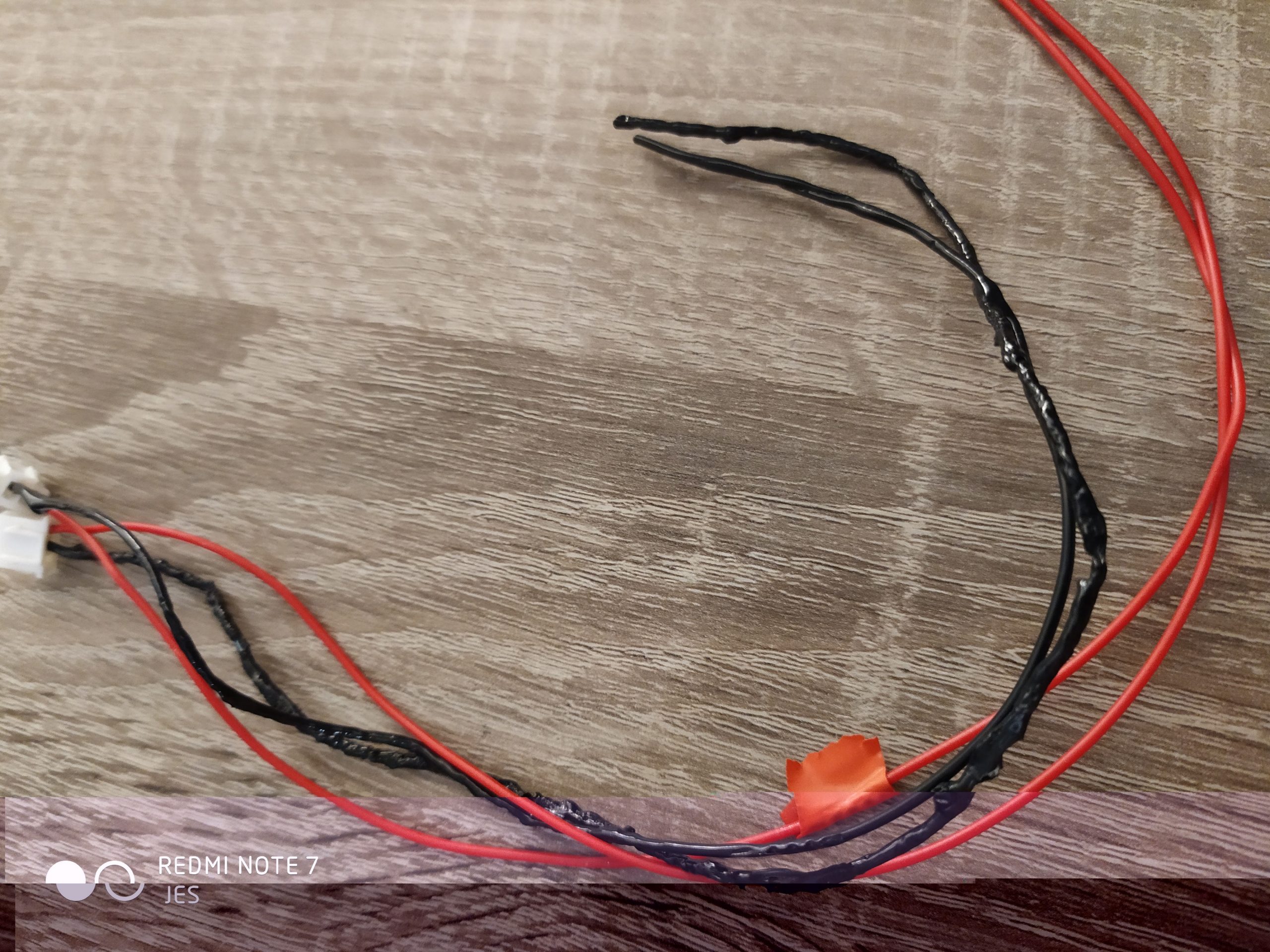
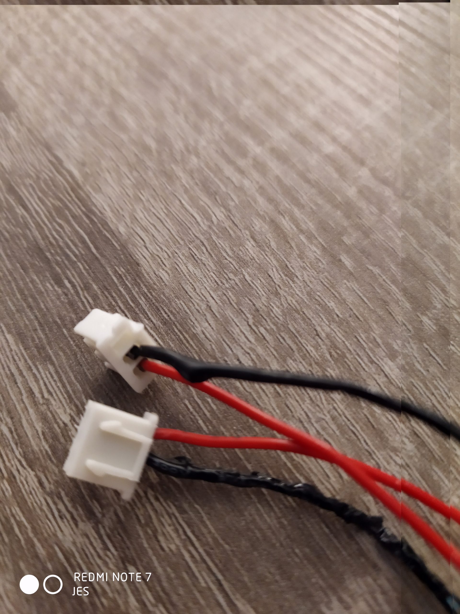
So, I use the regulator’s LOAD connectors to power two small displays which absorb less than 20mA each and show me some info on the solar system. One day something must have gone wrong (I disconnected the positive cable from a panel while system was all running, sunny day, circuit on) and the negative wire to my displays melted completely. I’ll show you what it looked like…
Actually, I didn’t expect anything to melt because I felt quite sure the regulator would keep everything under control, but obviously I was wrong. The displays didn’t burn out (yeeee!) but I didn’t feel safe anymore; what if it happens again? Could it start off a fire? Uhm… To avoid this happening again I wanted some circuit to protect my displays so I decided to make a small circuit on the fly using a couple of LM317 chips I had around. The LM317 is a very smart component, cheap and robust.
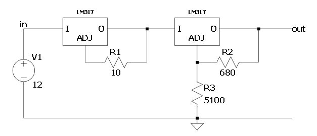
Here’s the schematics, the LM317 datasheet and the VC288 display datasheet.

The two LM317s are in series, the one on the left limits the current and feeds the second LM317 on the right, which instead limits the voltage. Input voltage coming from the solar panels should be between 12V and 19.5-20V (although the LM317 can handle higher voltage, see datasheet). The components I’m using are:
- 2x LM317 (TO-220 package)
- R1 10Ω (5W)
- R2 680Ω (1⁄4W)
- R3 5.1KΩ (1⁄4W)
The choice of the big cement R1 (5W) is because I don’t want it to melt, I didn’t actually do much calculations on R1 power, I simply choose the biggest resistor I had (yes… ehm… I’m no electronic guru!).
So, on the left side of the schematics, using a 10Ω resistor we have on the output pin (O) a circulating current of 0,125A (125mA which is well over the 40mA required by the two displays):
I = 1.25V / 10Ω = 0.125A (1.25V is the voltage between Out and Adjust pin of the LM317).
On the right side of the schematics, using the two resistors of 680Ω and 5.1KΩ we have an output voltage of:
Vout = 1.25 * (1 + R3 / R2) = 1.25 * (1 + 5100 / 680)
= 1.25 * (1 + 7.5) = 1.25V * 8.5 = 10.625V
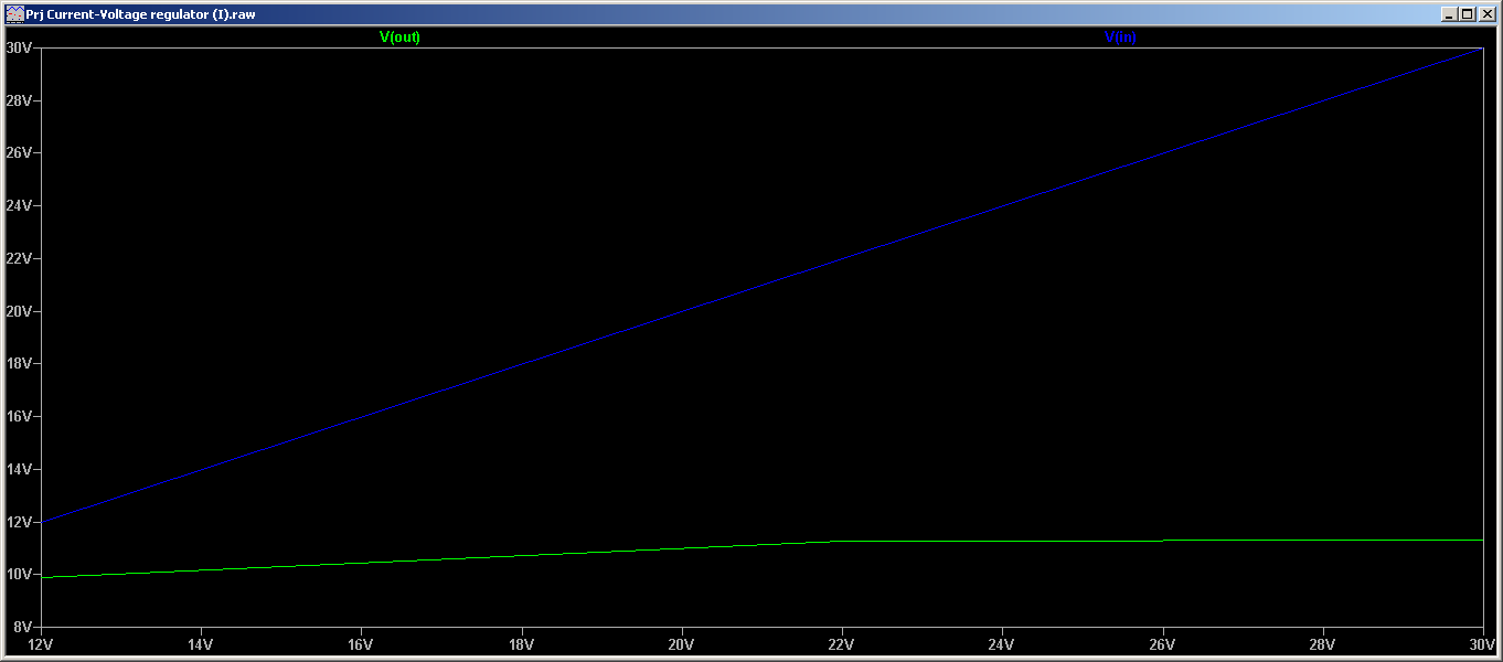
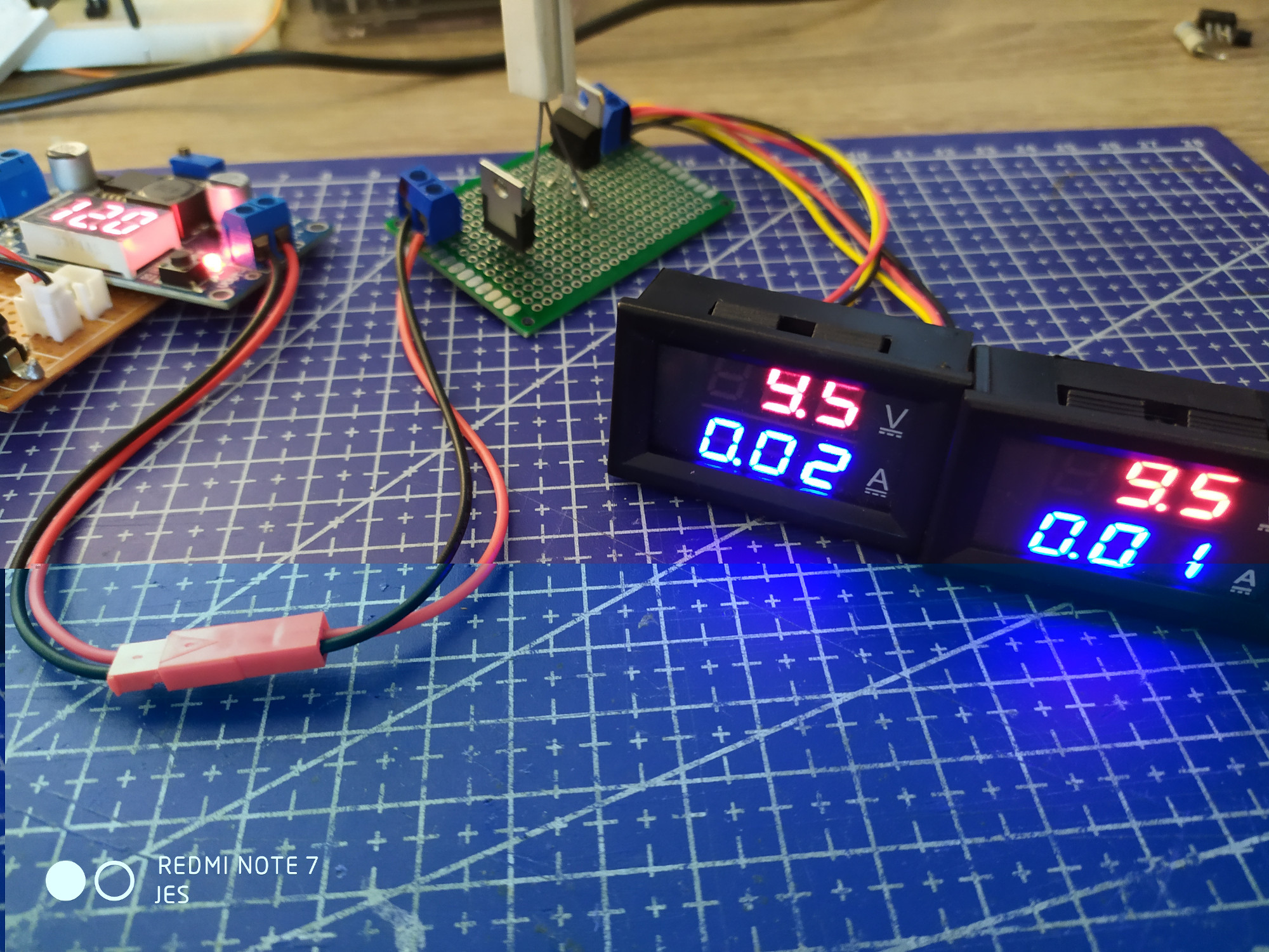
Simulating the circuit with LT Spice III this is the output we have (green line) when changing the input voltage (blue line) from 12V to 30V. You can see the LM317 keeps voltage under 11V value which is good enough for the displays.
Conclusions
My idea was to limit both current and voltage to be on the safe side. Not knowing what exactly came out of the solar regulator to melt my cables I suppose it was a great load of current because a high voltage would have probably burnt the displays.
This is the final circuit mounted between the regulators LOAD 12V output and the displays.
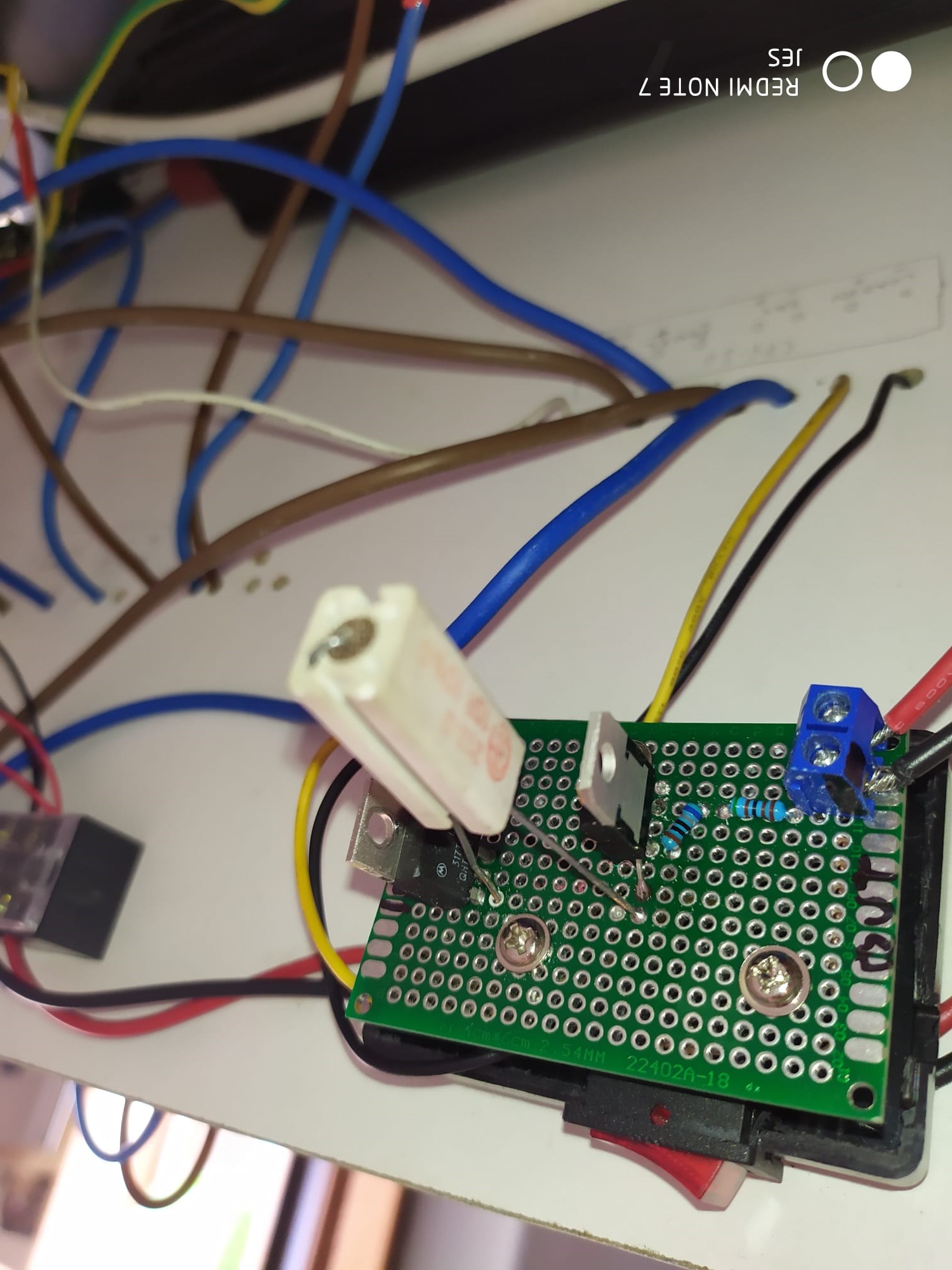
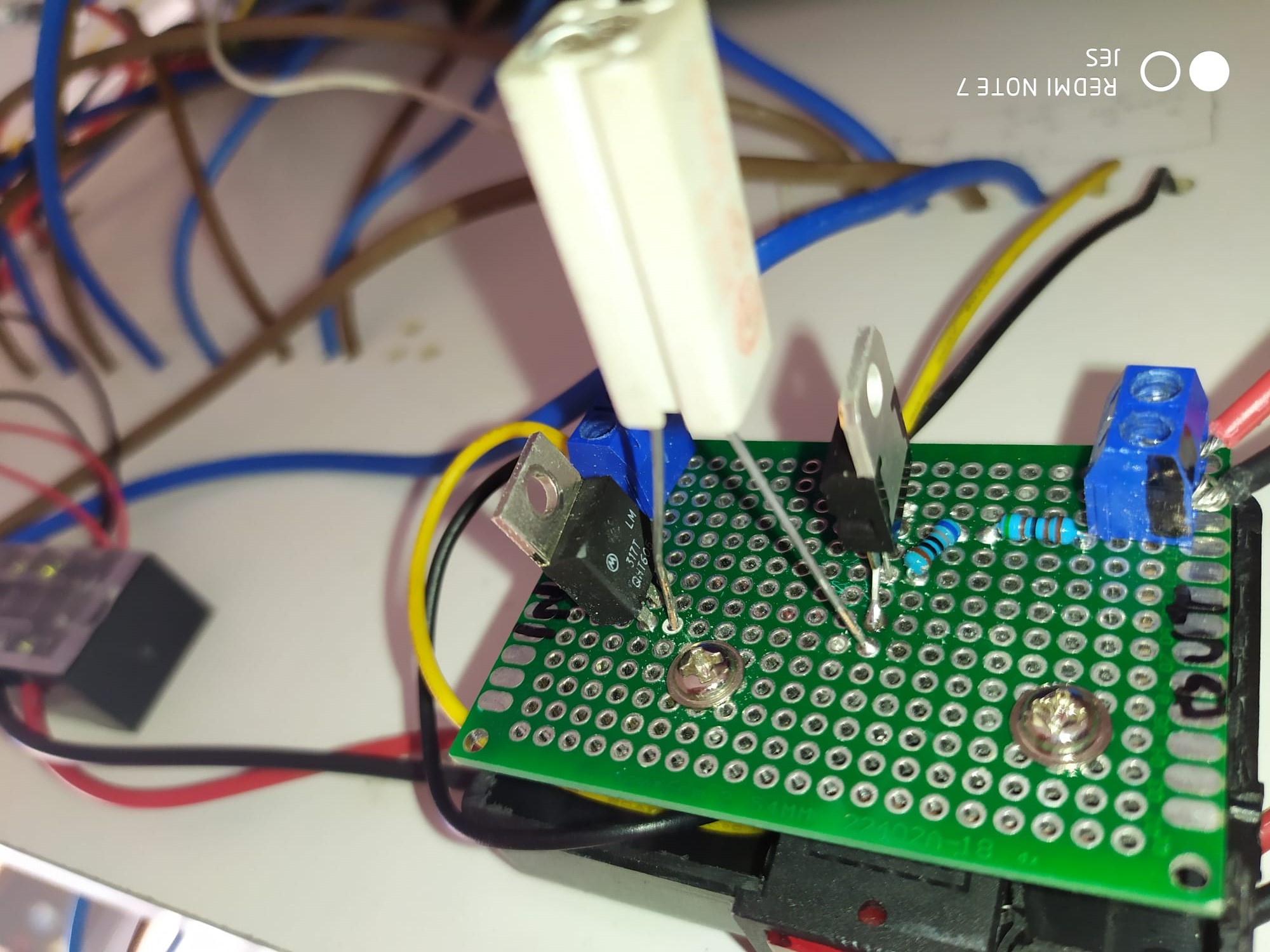
The circuit limits current to about 0,1A and voltage to 10.8V which are values in the accepted range for the displays.
It works very simple, first reducing current and then reducing voltage. I’m no electronic guru so I’m sure there’s better ways to do it… but this worked well. Please do suggest anything to make it better!
Thank you
great post, very informative. You must continue your writing. I am confident, you’ve a huge readers’ base already!
Thank you
Do you mind if I quote a few of your articles as long as I provide credit and sources back to your blog? My blog is in the exact same niche as yours and my users would truly benefit from some of the information you provide here. Please let me know if this okay with you. Appreciate it!|
Glad you like it, thank you! Sure, feel free to share
Today, while I was at work, my cousin stole my apple ipad and tested to see if it can survive a 30 foot drop, just so she can be a youtube sensation. My iPad is now destroyed and she has 83 views. I know this is entirely off topic but I had to share it with someone!|
Uhm, I don’t know if this current limiter could have helped… 😀
Great article.|
Thank you Eleonore
Appreciate the recommendation. Will try it out.|
[…] and voltage and connected it between the +/- Load Connectors and the display, schematics here http://electronic.acca3.it/2020/09/08/simple-dc-voltage-and-current-limiter/ […]
You have the current limit connected improperly, the load is connected after the 10 ohm resistor if you want current limiting function.
I’ll check that out Oz, thanks for pointing it out. I’d expect the current limited after the 10ohm resistor in any case, and the load connected to the following LM317 (on the right part of the schematics) not being able to pull more than 0.125A, but I might be wrong! I’ll do a test on the actual circuit and publish the results here in the comments.
I was using the LM317 + 1.25 ohm resistor for a 1A current limit and it works, but it needs a minimum of 3.3v headroom (from Vin to output after resistor). This did not work for my application discharging and checking for capacity of Li-Ion 18650 battery cells. So I found a better solution, LM1085 + 1.25 ohm resistor, and still pretty low cost from AliExpress. I also found this adjustable version that does not need a higher power pot. http://www.imajeenyus.com/electronics/20160530_adjustable_current_source/index.shtml
I didn’t know about the LM1085, good to know these higher amp rated versions, thank you for that. My first project based on an LM317 was an 18650 charger. My latest LM317 application, instead, made it last month, was to control the house’s water pump using a contactor and an ESP8266 (ESP8266 controls relay, relay controls contactor), a draft version of the project is here: http://electronic.acca3.it/2022/08/25/control-water-pump-using-esp8266/
I found another option, yes it is not super simple 2 component solution, but its nice to have options that has better dropout and higher current preformance. The tl431 + 1 transistor and 2 resistor circuit (check tl431 datasheet for circuit). Vref is 2.5v, this plus the drop on the transistor. I then found the TLVH431, it has half the Vref of the tl431 (1.25v vs 2.5v), and gives an extra 1.25v headroom, or lower voltage operating cutoff voltage, this also allows a lower power series pass resistor too, thus greatly enhancing the dropout voltage.
I found the circuit, interesting I must say; it uses a TIP31 transistor, maybe it’s the same one you found. My question is this: the whole reason for this circuit is because of the anomaly caused by disconnecting live FV panels, which caused cables to melt. Now, I’m quite sure the LM317 handles this anomaly; would the transistor & TL-431 be capable of handling the spike without burning out?
Now I understand your application, the solar panel is live when you disconnect it, and it sparks, correct?
I guess it depends on the transistor voltage rating, if it can handle the surge. Many transistors to choose from that would not burn out. Can you show the complete schematic with the lm317?
I dont know the solar panels connector type, can you give a link to the connector used?
Could you possibly toss a blanket or sheet over the panel to block the sun temporarily as you disconnect the connector?
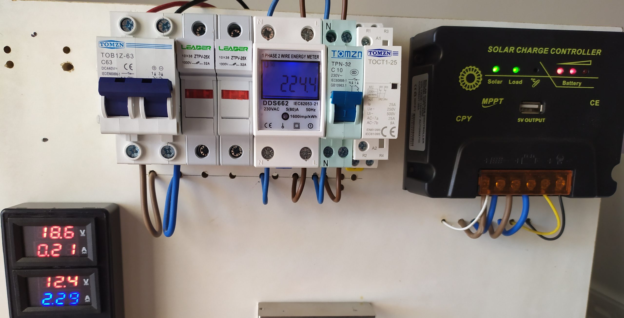
Nice to hear from you Oz 🙂 Yes, it was live when the problem occurred. Actually, there’s a 63A DC MCB breaker to disconnect panels, but that time I forgot to disconnect it maybe because it was one of my first experiments. Now I always switch the MCB before servicing. The complete schematics is the one you see in the photo, there’s nothing else. Connectors are standard MC4 rated 1000V; and the cables from the panels to inside the house travel for 10 meters and cross two derivation boxes (a box near the panels and another box and another one before entering the house).
Here there’s the photos of the panels and of the control panel with the MCB: http://electronic.acca3.it/2020/05/31/impianto-fotovoltaico-a-basso-costo/
You can see the small black derivation box on the wall in the photo with the mounted panels. Sorry, the article is in italian, but the photos and the graphic diagram should be quite clear.
Google translate turned it into english for me, haha.
Now I got an idea on what your application is, why the lm317 constant current mode for?
(google search brought me to your page and I noticed the wiring error you had)
When running a solar system, I think efficiency (EFF) is king, especially on a budget.
Instead of linear regulators, buck regulators would be better. Many dcdc buck regulators that have settable CV and CC pots.
For batteries, I think lead acid is the worst technology. Its got a horrible cycle life and they are not great for taking them down to lower SOC voltages (even agm), this hurts the life cycles, generally all batteries this is true, but lead acid is the worst.
I would of went with Li-Ion Or LiFe. For example these are grade B cells and 80Ah, but test to 50Ah.
https://jag35.com/collections/new-arrivals/products/lg-nmc-pouch-cells-71ah-80a-continuous-160a-burst-bgrade
I am not saying these are in your budjet, just an option.
7 cells, make a 3s2p pack configuration, for 11.1v 100Ah 550Wh pack and have a spare cell.
Or a 7s1p pack for 24v 50ah 1300Wh pack. Just saying there are a lot of better options than lead acid.
I found a place that had these cells for half price ($8/cell, but they sold out), I was going to build a 10Kw powerwall pack (13s4p, 48v 20Ah) for $500 shipped (cells only), this smokes any powerwall deal that i have seen.
😀 Google translate saves our life! Lately I’m using it to translate from… Chinese to english! LOL
The LM317 only protects the two displays, nothing else. This small solar system has a 20A MPPT controller (15€) and deep cycle AGM 45AH battery (15€ each, 9AH 12V, 5 in parallel), they are real cheap; the system gives power to my notebook, nothing else! AGM deep cycle Lead acid only give around 50% of nominal capacity, but they’re perfect for low budget projects.
Going to batteries, yes, I’m making a bigger solar system (1.6KW of panels) with 1120 Li-Ion 18650 cells… very big project for me and I have little time! I’m making four 14s20p 44Ah batteries, in parallel = 176Ah. Each cell, 80-90% capacity costed around 0.75€, quite good. For now I made the busbars and must make the metal structure to hold the panels… I’m very slow 😀
Where are you in the world Oz?
Thanks for the help