Arduino DC current measurement problems
Reading DC current using ACS712 with ±0.1A accuracy
Tags: Automation, IoT, Photovoltaic, Solar, Current
Sooner or later all “micro-programmers” want to measure current with Arduino family boards. It can be quite tricky and many different approaches are available on the Internet showing possible solutions. This article demonstrates a setup to obtain an acceptable error in readings. The used chip is Allegro’s ACS712, the datasheet reports specifications and typical/maximum operating parameters for the ACS712.
The most common problems in using ACS712 chip are floating readings and correcting noise influence. The proposed solution comes from in-depth research based on is based on calculating average from multiple reads and applying an alpha filter to results. Alpha filter is the algorithm used for accomplishing noise smoothening down to an acceptable value.
This article will go through a first testing phase and then shows Arduino code used for tests:
- First Test : ACS712 with NO LOAD, with and without software filtering
- Second Test : ACS712 with 2 ampere DC LOAD, with and without software filtering
- Third Test : ACS712 with 5 ampere DC LOAD, with and without software filtering
- Notes on board setup and code : Source code compiled in Arduino IDE 1.8.10 and notes
Goal: The goal to achieve is a ±0.1A accuracy on current readings.
Setup
For the test setup these pieces are used:
- A compatible Arduino UNO R3 board It’s surely possible to repeat the test using other microcontrollers (ESP32, ESP8266, ATtiny). Arduino is powered from USB which is used as serial monitor to gather read values.
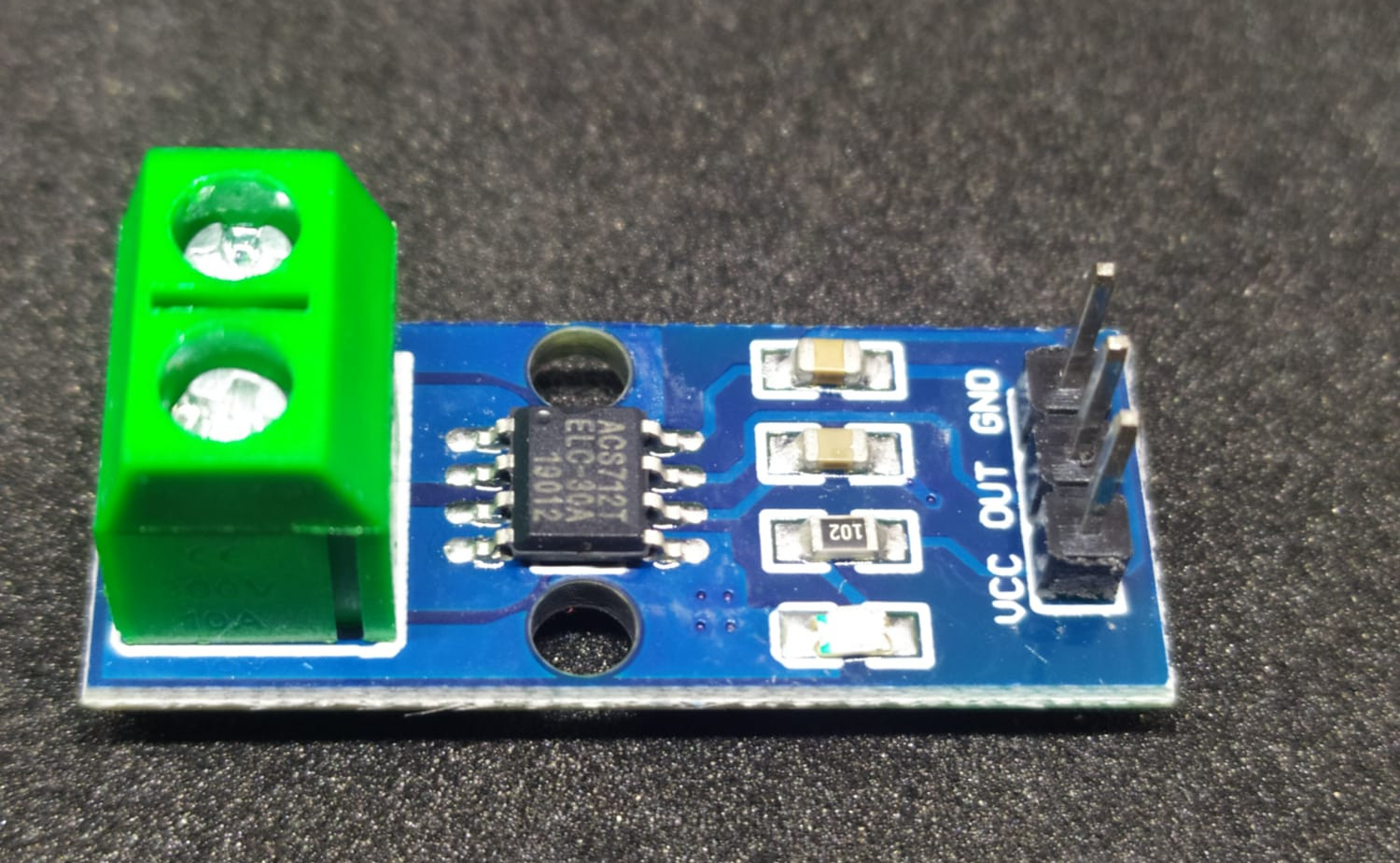
- A 30A ACS712 board, it’s possible to use different versions of ACS712 board (5A or 20A versions).
- Load is a car light bulb, type H7 55W 12V two pin lamp, a single one for 2A test and two in parallel for 5A test.
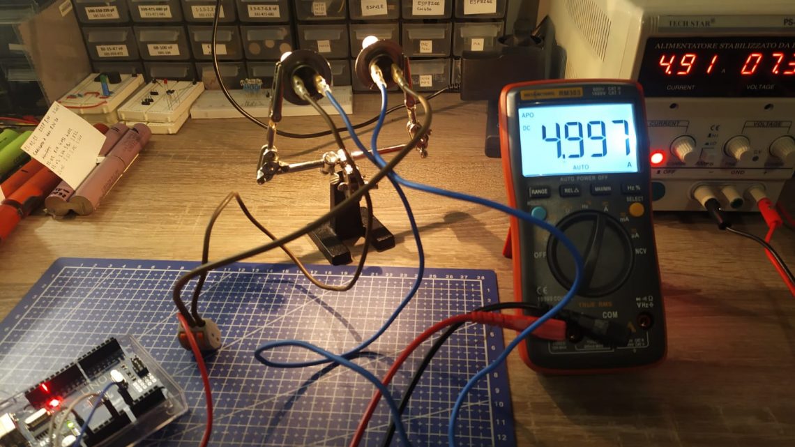
- Measurements are done with RichMeters RM303 with an accuracy of ±0.8%+3. DMM is set in DC ampere mode, with probe inserted in 10A connector.
- DC Power Source is TechStar PS-305D 30V 5A power supply in CC (constant current) mode.
Boards can be bought from AliExpress using below affiliate links: fast shipping is usually in 15-20 days, normal shipping is usually in 45-60 days.
| Product | Description | Price (fast Shipping) | Price (normal Shipping) |
 | Arduino UNO R3 | Buy 5pcs ALIEXPRESS | Buy 1 ALIEXPRESS |
 | ACS712 board 30A | Buy 1pcs ALIEXPRESS | Buy 1 ALIEXPRESS |
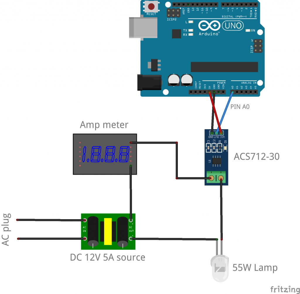
Connections are straighforward from ACS712 board to Arduino: VCC to Arduino’s 5V pin, GND to arduino’s GND pin and OUT pin to Arduino’s A0 analogic pin.
The light bulb is connected with one pin to positive terminal of DC source. The other pin from the light bulb is connected to one pin of the green connector on ACS712. The second pin on green connector is connected in series with the one cable from the DMM, in series with negative terminal of power source.
First Test: ACS712 with no LOAD
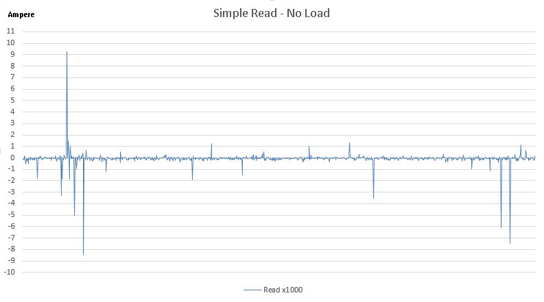
This setup is with no load applied on the ACS712 boards input pins which are left floating. The expected result here is to read 0.0A. That doesn’t happen because of fluctuations caused by external noise and noise in the current signal, which are relevant. The results without applying any kind of smoothing/averaging isn’t consistent. The following graph represents the results based on 1000 consecutive reads (with no delay in between analogue reads and no dummy read). Peaks are well visible.
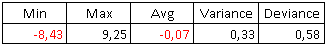
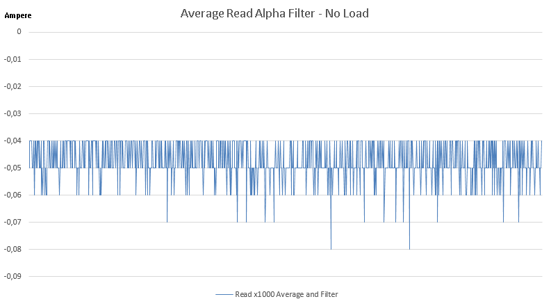
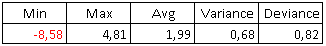
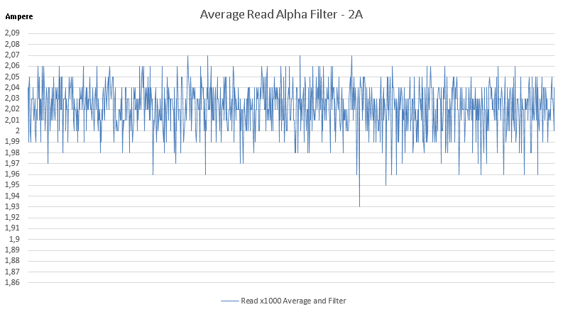
Applying averaging and alpha filter on data readings permits to contain error within the ±0.1A range given as a goal. In figure 2 results are reported for a no-load test on 1000 consecutive iterations. Each iteration does another 1000 analogue reads, for a total of 1 million reads from the sensor, and values are both averaged and alpha-filtered. The maximum measured error is ±0.08A, well within the ±0.1A requirement.
Second Test: ACS712 with 2A DC Load
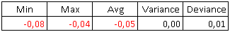
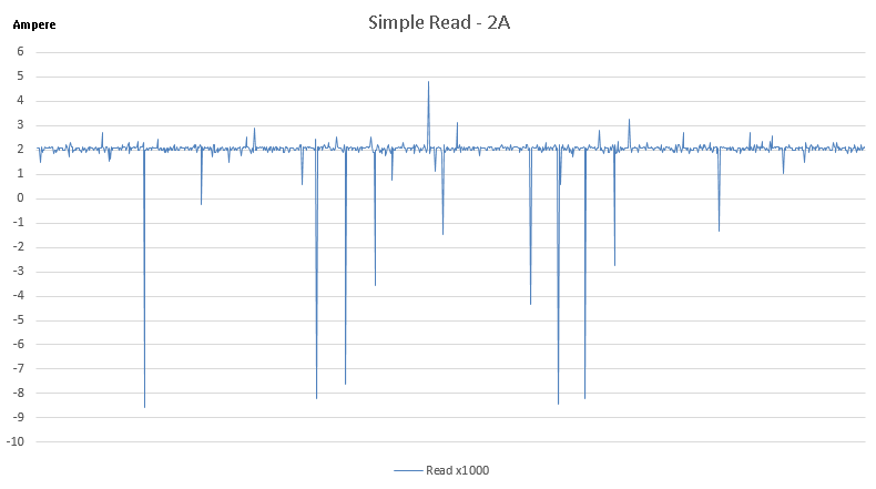
Second test shows behaviour under a small 2A DC load. As visible in following figure 3 noise impact is quite relevant under load, too, and makes resulting data unusable. Peak readings of noise range from nearly +5A to over -8A.
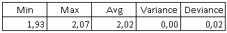
Again, we can obtain much better results applying averaging and alpha filter on data readings, containing error within the ±0.1A goal. The minimum value read is 1.93A and maximum is 2.07A.
Third Test: ACS712 with 5A DC Load
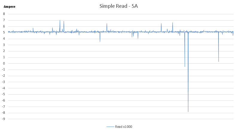
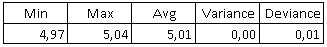
The third and last test is performed using a 5 ampere DC load and results are consistent with previous tests showing a linear behaviour of ACS712 board. The 1000 consecutive analogue reads, without any software filtering, suffer from noise readings and have peaks ranging from +7A to nearly -8A.
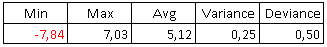
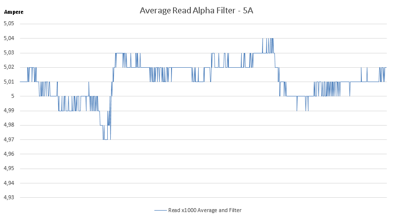
Last graphic in figure 6 shows results using a 5A DC load and applying average and alpha filter. Resulting values are much more stable than the 2A test showing a range from 4.97A to 5.04A, confirming the validity of software filtering.
Full Code
Code is written for both modes, simple analogue read mode and software corrected mode. The first program simply reads analogue port printing values and without applying any noise reduction. The second program reads analogue port and applies average and alpha filter.
/**
 * ACS712 30A Simple ACS712 analog read (no software correction).
 * Serial port is set to 115200 bit/second for better speed.
 * Values printed are measured in amperes units.
 * @author Julian E.Spina (jes@acca3.it)
 */

//float sensitivity = 185.0f; // Uncomment for 5A board, Output sens. 185mV/A
//float sensitivity = 100.0f; // Uncomment for 20A board, Output sens. 100mV/A
float sensitivity = 66.0f; // Uncomment for 30A board, Output sens. 66mV/A

int adcValue= 0;
const int currentPin = A0;
float adcVoltage = 0.0f;
float currentValue = 0.0f;
int ARDUINO_REF = 5000;
int offsetVoltage = ARDUINO_REF / 2;

void setup() {
  Serial.begin(115200);
  delay(2000);
}

void loop() {
  for (int i=0; i<1000; i++)
    doSimpleRead();
  while(true) ; // Do nothing
}

// Simple reading without any correction
void doSimpleRead() {
  analogRead(currentPin); // Dummy read, doesn't help
  adcValue = analogRead(currentPin);
  adcVoltage = (adcValue / 1024.0) * ARDUINO_REF;
  currentValue = ((adcVoltage - offsetVoltage) / sensitivity);

  Serial.println(currentValue, 2);
}
Following code is the version which calculates average and applies alpha filter on data, giving a result where noise is smoothened down to keep output accuracy in the ±0.1 ampere range.
/**
 * ACS712 30A with ±0.1A accuracy using average and alpha filter.
 * Serial port is set to 115200 bit/second for better speed.
 * Values printed are measured in amperes units.
 * @author Julian E.Spina (jes@acca3.it)
 */

//float sensitivity = 185.0f; // Uncomment this for 5A board, Output sensitivity 185mV/A
//float sensitivity = 100.0f; // Uncomment this for 20A board, Output sensitivity 100mV/A
float sensitivity = 66.0f; // Uncomment this for 30A board, Output sensitivity 66mV/A

int adcValue= 0;
const int currentPin = A0;
float adcVoltage = 0.0f;
float currentValue = 0.0f;

int ARDUINO_REF = 5000;
int offsetVoltage = ARDUINO_REF / 2;
float errorCorrectionAmp = 0.0f; // Set this to use a correcting offset on readings, e.g. -0.15f;
const float alpha = 0.1f; // Can vary this value between 0.1 and 0.9, changes filter impact

void setup() {
  Serial.begin(115200);
  delay(2000);
}

void loop() {
  for (int i=0; i<1000; i++)
    doReadAlphaFilter();
  while(true) ; // Do nothing
}

// Reading and apply software correction
void doReadAlphaFilter() {
   float average = 0.0f, previousValue = 0.0f;

   analogRead(currentPin); // Dummy read, doesn't help

   for(int i = 0; i < 1000; i++) {
      adcValue = analogRead(currentPin);
      adcVoltage = (adcValue / 1024.0f) * ARDUINO_REF;
      currentValue = (((float)(adcVoltage - offsetVoltage)) / sensitivity);

      if (i>0)
        currentValue = alpha * currentValue + (1-alpha) * previousValue;

      average += currentValue;
      previousValue = currentValue;
   }

   Serial.println(average / 1000.0f + errorCorrectionAmp, 2);
}
Notes on board setup and code
Two different ACS712 boards, both 30A version, were used for tests, obtaining similar results. Different approaches were tested in code:
- Dummy reading from analogue pin before effective reading: no appreciable difference in results;
- Delay between analogue readings: no appreciable difference in results.
Also a hardware modify was tested on ACS712 board:
- Extra 1nF ceramic capacitor soldered on C2 capacitor (most external capacitor on board): no appreciable difference in results.
Works like a charm for me but not for AC current.
I’ll be releasing the AC version soon, thanks for reading
Very nice blog – do you already have the AC versions with the alpha filter? Good job!
Thanks a lot!! For AC version I used a similar alpha filter, I suppose I’ll publish the code in the weekend. What I had to do for AC, although, was to correct the reading which was always a bit too high, compared to the energy meter and the mains display. I did that by adding manual fixes in the code: if reading<1.5A result=result*0.93; when reading between (1.5 and 2.5) result=result*0.94; between (2.5A and 8.0A) result=result*0.97; and so on. [EDITED]
I will try it right now – will keep you informed about the results. Thank you and greetings from Brazil. 🙂
Heya i am for the first time here. I found this board and I find It really helpful & it
helped me out much. I hope to provide something again and aid others
such as you helped me.
[…] Reference: Here’s the link to the DC version of the board I made some time ago http://electronic.acca3.it/2021/03/21/arduino-measure-current-problem/ […]
[…] is the AC version of the program I published last year with that nifty alpha filter algorithm. It has a very small memory usage and runs on both Arduino […]
Hi all,
I am using an Arduino to measure amps from a setra model 265. I am also using the acs7125a chip. It does not matter what or who’s program I use it still does not change the readings. I will try this code as well but I am not confident it will work. The output of the transducer is 4-20mA. I am feeding the 265 with 24V dc and using a pico tube to measure airflow. FYI.
Thanks for any input.
Don
Hi there. This is an interesting problem and I don’t think you can use an ACS712 to measure such a low current and with the resolution you need. I managed to get a +/-500mA (0.5A) precision which is no good for your 4-20mA range. Now, this takes me out of my comfort zone, but I can tell you how I’d start the research to find a solution. You’re using a DC source so that’s good. I’m sure I don’t know the exact solution but I can tell you what I’d do to find it, it’s a bunch of ideas, I always prefer to explore as much as possible before going ahead. When using Arduino with external DC currents I check two things: 1) the precision I need, so I’m not sure Arduino’s input pins have enough precision with their 12 bits; in case you can use a 16 bit module (ADC1115) to get the resolution you need. Next, the output voltage: it’s true you get an output in mA but to feed it into an Arduino’s pin you must be sure it’s not over 5V; if it’s higher than 5V you must a) reduce it before giving it in input for e.g. by using a voltage divider made by resistors or something better or b) use an Arduino module which can handle higher voltages (the INA219 manages up to 26V and has a resolution of 0.1mA, enough precision for your scenario). In any case it’s good to know exactly what’s coming out of the Setra’s pin, so you can choose the best solution, and if your solution requires feeding Setra’s output into an Arduino pin you must be sure about the voltage, too.
In your 4-20mA output how many measurements can you get? If the Setra 265 can give you 32 different measurements (4mA, 4.5mA, 5mA, … 19.5mA, 20mA) then the resolution of the INA219 is sufficient because it can measure up to 0.1mA, better than the 0.5mA of the example. Consider that working with Arduino and DC currents usually requires that the GND pin (the common ground, logical 0V) of Arduino and of the external DC you’re using must be in common, that means connected together, so that the measurements have a common 0V reference. I would check the output of the Setra 265 with both a DMM set on mA and with an oscilloscope (I have a super cheap 35$ DSO150 model) to see if it’s the DC output I’m expecting (and not a sine wave, which is more difficult to handle and cannot be fed in input to Arduino’s pins). I did a quick search in the web to see how others approach this problem and the best solution seems to use a shunt resistor measuring the voltage drop (again Arduino’s 12 bit ADC could not be sufficient to measure small variations, a 16 bit ADC would be better). Hope this helps, if you update me on your progress I’ll be glad to know about it!
So first, Thanks for the input. So you are saying I need to put some resistors in the system to reduce the voltage. I have 24V dc going into the Sentry. I will search to find out what I can do to reduce the voltage to get 24V to under 5V.
If you have any other ideas I would love to hear them since I am new to this.
Thanks again.
Reduce the voltage (actually, check that the voltage is <=5V) only if your solution will be to connect the Sentry output directly to the Arduino pin, without the ACS712. As I said I don't have a solution (yet!) because I don't exactly know what signal comes out of the Sentry. Before going ahead I'd surely analyse that 4-20mAh output PIN to discover the voltage and the current type (I suppose it's a DC current). ACS712 doesn't have enough precision to measure it. INA219 might be OK. A shunt resistor could work. But it any case you must know get this info about the Sentry's output. Thank you, it's good to learn new things!